Why Choose CNC Cutting for Your Manufacturing Needs?
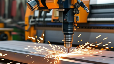
Manufacturers often compare cutting methods by speed, accuracy, waste, and repeatability. Cnc Cutting follows programmed toolpaths to shape sheet, plate, or other stock with less operator-to-operator variation. Depending on the equipment, it may use a router, laser, plasma, or waterjet process. That range matters: each method suits different materials, thicknesses, edge requirements, and shop conditions. In a well-run shop, a digital drawing can guide consistent parts across a short prototype run or a larger batch. Small details matter.
The real advantage is not simply automation; it is control over a repeatable process. Repeatable paths can reduce layout errors and make revisions easier when dimensions change. Yet CNC is not automatically cheaper or more precise for every job. A thin aluminum bracket with clean contours may be straightforward, while thick plate or heat-sensitive material can demand different settings and inspection. Material thickness, kerf, fixturing, and edge finish should be reviewed before production begins. Clear drawings and a first-article check can catch fit issues before they multiply across a batch. This article examines where CNC cutting adds value, what limitations to expect, and how to match a process to a part. The goal is a practical decision, not a promise of perfect results. Even careful setups need checks.
What CNC Cutting Means: Automated Motion and ISO 6983 G-Code
Why Choose CNC Cutting for Your Manufacturing Needs?
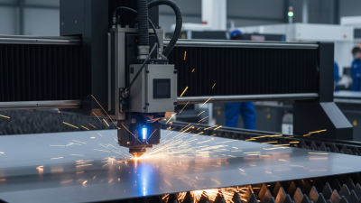
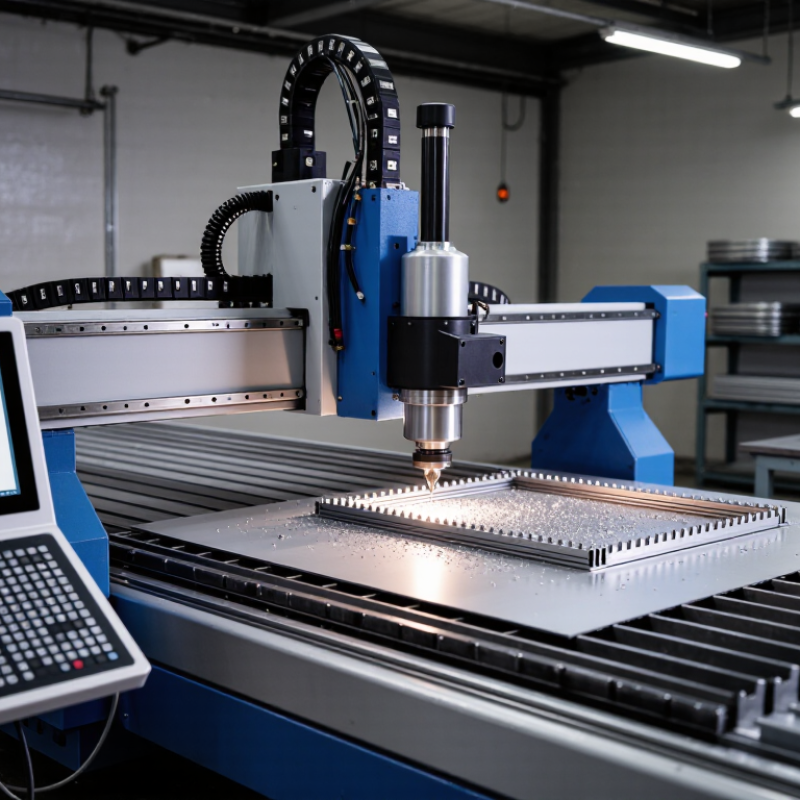
CNC cutting turns a digital toolpath into controlled machine movement. The controller reads instructions commonly written in ISO 6983 G-code, then coordinates axes, feed rate, and cutting actions. A flat sheet moves beneath a cutting head, or the head travels across a fixed workpiece. Either way, programmed motion helps produce repeatable dimensions. Small errors still matter.
G-code describes practical commands, such as positioning a tool, setting a feed rate, or pausing between operations. The exact code and machine behavior can vary by controller, so a file should be checked against the equipment’s setup. In production, operators inspect the first cut, measure edges with calipers, and adjust focus, speed, or holding methods when needed. Automation improves consistency, but it does not remove judgment. A poorly secured sheet can shift, and even a sound program may need refinement.
Tips: Confirm units, work offsets, and material thickness before cutting. Run a test on scrap. Keep a close eye on the first pass; it can reveal a setup issue that the screen will not show.
Why Choose CNC Cutting for Your Manufacturing Needs? - What CNC Cutting Means: Automated Motion and ISO 6983 G-Code
| Dimension |
What It Means |
Manufacturing Relevance |
| Automated motion |
A CNC controller coordinates machine movement according to a programmed toolpath. |
The same program can guide repeated operations, subject to machine setup, tooling, and process conditions. |
| ISO 6983 program format |
ISO 6983 specifies a format for programs used with numerically controlled machines; commonly used programs include G- and M-codes. |
A defined program structure helps communicate motion and machine functions. Supported codes and behavior can vary by controller. |
| Axis movement |
Programs can command movement along linear axes and, on suitable machines, rotary axes. |
The available axes determine which cuts, contours, and orientations a machine can produce. |
| Toolpath interpolation |
Common motion commands describe straight-line moves and circular arcs between programmed positions. |
These moves allow the tool to follow straight edges, curved profiles, and other planned geometries. |
| Feed rate and spindle control |
Programs may specify tool feed and spindle-related commands where the machine and process support them. |
Appropriate settings depend on material, cutting tool, machine capability, and operation. |
| Repeatability and quality |
A stored program can reproduce a specified sequence of machine movements. |
Finished-part consistency also depends on calibration, workholding, tool condition, material, and inspection. |
| Cutting process |
CNC cutting can be performed by different processes, including milling, turning, laser, plasma, and waterjet cutting. |
The suitable process depends on the material, part geometry, required edge quality, and production requirements. |
How CAD/CAM Turns a Digital Design into Machine Toolpaths
Why Choose CNC Cutting for Your Manufacturing Needs?
How CAD/CAM Turns a Digital Design into Machine Toolpaths
CAD/CAM software connects a part’s digital geometry to the movements of a CNC machine. The designer creates or imports a CAD model, then defines material, stock dimensions, and machining operations. CAM software calculates toolpaths, such as contour cuts, pockets, and drilled holes. These paths become machine instructions that guide the cutting tool across the workpiece. Small details matter: a sharp internal corner may need a smaller tool or a revised design.
A machinist reviews more than the screen preview. They select a tool, set feeds and speeds, establish the work origin, and check how the part will be held. Simulation can reveal collisions or excess cutting, but it cannot guarantee a perfect result. Material variation, tool wear, or an imperfect setup may still affect the finished part. A first article inspection helps catch those issues before repeat production. It takes time. That time is useful.
Tips: Confirm the stock size and machine setup before generating toolpaths. Simulate the program, then inspect the first cut. If a feature looks awkward to machine, revisit the design rather than forcing the toolpath.
Which CNC Cutting Methods Suit Metals, Plastics, and Wood
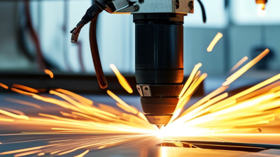
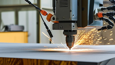
CNC cutting works best when the method matches the material, thickness, and required edge quality. For sheet metal, laser cutting can produce narrow kerfs and detailed profiles quickly. It is often a practical choice for stainless steel and mild steel. Reflective metals may need careful process settings, and heat can affect the cut edge. Waterjet cutting avoids a heat-affected zone, which can help with heat-sensitive alloys or thick stock. It is slower in some jobs and may leave a slightly tapered edge. Not always.
Plastics need a different kind of care. A CNC router or milling machine can shape acrylic, polycarbonate, and engineering plastics with controlled tool paths. Sharp cutters and suitable feed rates help reduce melting, chips, and rough edges. Acrylic can crack or chip if it is poorly supported. That detail matters. For thin plastic sheets, laser cutting may create clean shapes, but heat can leave a melted edge or visible fumes. Testing a small sample is sensible before committing to a full sheet.
Wood is commonly cut with CNC routers using end mills or specialized router bits. The right bit and a firm hold-down can limit tear-out, especially around knots and grain changes. Plywood cuts predictably, while solid wood can move as moisture changes. Results vary. A toolpath that looks perfect on screen may still need adjustment after the first pass, so operators should inspect the actual edge and fit before running a large batch.
How CNC Tolerances Are Specified: ISO 2768-m Allows ±0.1 mm for 0.5–6 mm
CNC cutting can produce consistent parts, but the drawing must define what “consistent” means. ISO 2768-m provides general tolerances for dimensions that have no individual tolerance specified, when the drawing calls for that standard. For a nominal size from 0.5 to 6 mm, the medium class allows ±0.1 mm. A 4 mm feature, for example, may measure from 3.9 to 4.1 mm. That matters.
This allowance is not a promise that every CNC process will hold the tolerance under all conditions. Tool wear, material movement, clamping, and measurement methods can affect the result. A small slot near a thin wall may behave differently from a simple outside edge. It is easy to assume the standard covers every feature, but individually toleranced dimensions and geometric requirements need their own callouts. A second look can prevent costly confusion. Before cutting, confirm that the drawing names ISO 2768-m and identifies critical dimensions separately. Then inspect representative features with suitable measuring equipment, such as calipers or a micrometer. The standard creates a shared baseline; clear drawings and process checks make it useful in production.
Why Choose CNC Cutting for Your Manufacturing Needs?
How CNC Tolerances Are Specified: ISO 2768-m allows ±0.1 mm for linear dimensions from 0.5 to 6 mm.
The chart shows the permitted bilateral tolerance magnitude for each nominal-size range under ISO 2768-1, tolerance class m. For example, a 5 mm dimension with no individually specified tolerance may be 4.9–5.1 mm. General tolerances apply only where a drawing does not specify a tighter or otherwise individual tolerance; actual CNC capability depends on the material, part geometry, tooling, and process.
Why Manufacturers Choose CNC: Repeatability, Material Use, and Scalability
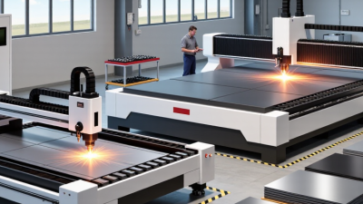
CNC cutting supports repeatability by following the same programmed toolpath across production runs. With stable fixturing, calibrated tools, and verified settings, parts can fit together with less manual adjustment. That matters when a shop makes hundreds of brackets with matching holes and edges. Still, a CNC machine cannot correct a poor drawing or a worn tool on its own. Checks remain essential.
Material use depends on the design and cutting strategy. Nesting parts closely on a sheet can reduce offcuts, while suitable toolpaths limit unnecessary passes. Results vary with material thickness, grain, and part geometry; savings should be measured, not assumed. For scaling, CNC programs can move from prototypes to repeat orders with fewer process changes. Deloitte and MAPI’s 2019 Smart Factory Study found that 86% of surveyed manufacturers viewed smart factory solutions as a future competitiveness driver. That broader finding supports investment in connected production, but it does not guarantee a return for every CNC cell.
Tips: Track scrap rate, cycle time, and first-pass inspection results for each job. Review them before increasing batch size. Small checks catch costly drift.